
Core & distribution
Up to 25.6 Tbps chassis capacity
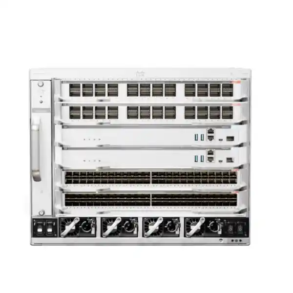
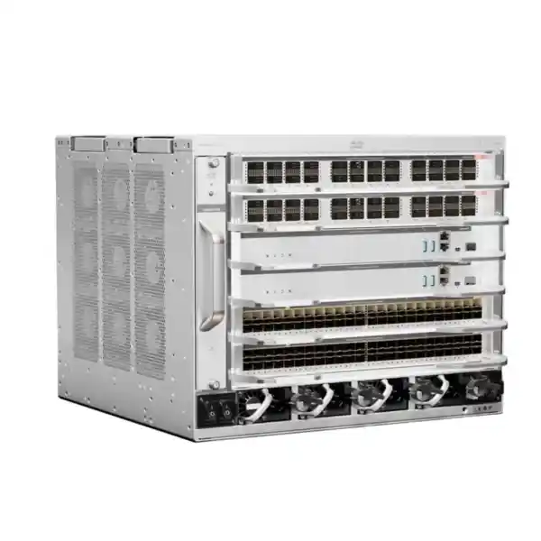
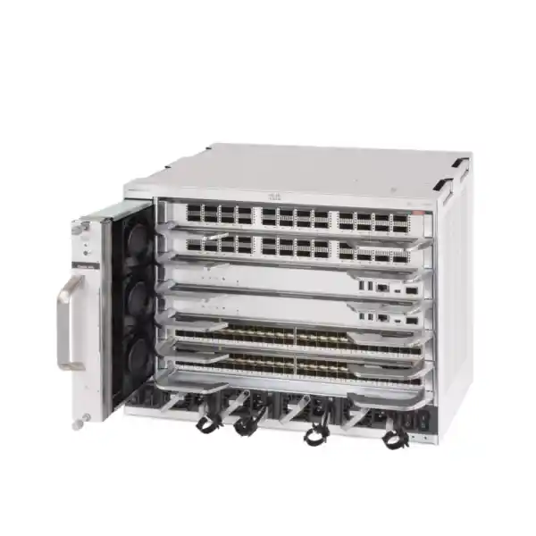
Cisco Catalyst C9606R Network Switch Chassis
Build a resilient, high-capacity campus core around a modular platform that can be configured for the port speeds, redundancy model, and growth path your network actually requires. The Cisco Catalyst C9606R is the six-slot chassis at the heart of the Catalyst 9600 Series, designed for enterprise core and distribution roles where a fixed-port switch may not provide enough expansion flexibility or component redundancy.
Important buying note: C9606R is a modular chassis, not a complete standalone switch configuration. A deployable system requires compatible supervisor engine, line card, power, software, and connectivity selections. Request a configuration review before ordering so the chassis is matched to the required uplinks, port density, resiliency, rack, and power design.
Who the C9606R is for
The C9606R is most relevant when the switching layer is expected to carry a large amount of east-west and north-south traffic, aggregate many access switches, support high-speed server or service links, or provide a highly available routing and switching point for a large campus. Typical buyers include enterprises refreshing an aging campus core, universities and education campuses, hospitals and other multi-building institutions, large offices, public-sector environments, financial organizations, industrial campuses, hospitality groups with centralized aggregation, and service organizations that want a modular platform rather than a collection of unrelated fixed switches.
Its value comes from configuration choice. The same chassis can be built around different supervisor and line-card combinations, allowing the network team to emphasize 10/25/50G access aggregation, 40/100G core connectivity, multigigabit copper, or higher-speed 200/400G paths where supported by the selected hardware. This flexibility is useful when the immediate requirement is substantial but the exact port mix is expected to evolve over the network lifecycle.
For Tanzanian deployments, the design discussion should start with the real site topology: how many buildings or access blocks feed the core, whether the design uses a collapsed core or separate core and distribution layers, what uplink speeds are needed today, what speeds are likely during the next refresh cycle, and what level of component redundancy the organization can justify. Those questions determine whether the C9606R is the right platform and, if it is, which modules should be included in the bill of materials.
C9606R at a glance
What the chassis includes—and what it does not
A common purchasing mistake with modular switching is to treat the chassis part number as though it were equivalent to a fixed switch with a predetermined set of Ethernet ports. The C9606R should instead be treated as the physical and electrical platform into which the rest of the switching system is built. Cisco’s current product documentation describes a fully assembled Catalyst 9600 system as including the chassis, at least one supervisor engine, at least one line card for network connectivity, a fan tray, and at least two power supplies. The exact required components depend on load, power input, resiliency target, and selected modules.
That distinction matters during budgeting because the final project cost is not determined by the chassis alone. A complete bill of materials may include a second supervisor for in-chassis redundancy, one or more line cards, additional power supplies for the intended redundancy mode, software or subscription licensing, rack hardware, power cords, transceivers, fiber or copper cabling, patching, spare optics, and support services. Where the design spans two chassis, inter-chassis connectivity and the chosen high-availability architecture must also be considered.
Chassis foundation
Provides the slots, backplane architecture, power-supply bays, cooling system, rack footprint, and mechanical platform for the modular switch.
Configuration components
Supervisors and line cards determine control-plane capabilities, interface types, per-slot bandwidth, port density, and the practical role of the completed system.
Deployment accessories
Optics, cabling, rack kits, power feeds, software entitlements, and other accessories must be selected against the actual topology and site requirements.
Verified chassis specifications
| Specification | C9606R | Why it matters |
|---|---|---|
| Total slots | 6 | Separates supervisor and interface expansion roles. |
| Supervisor slots | 2, dedicated slots 3 and 4 | Supports redundant supervisor design. |
| Line-card slots | 4, slots 1, 2, 5 and 6 | Allows port density and media type to be tailored. |
| Supported supervisor families | C9600-SUP-1 and C9600X-SUP-2 | Supervisor choice changes bandwidth and feature considerations. |
| Maximum per-slot bandwidth | Up to 6.4 Tbps with C9600X-SUP-2; up to 2.4 Tbps with C9600-SUP-1 | Important for high-density 100G/400G designs. |
| Power-supply bays | 4 | Supports capacity and N+1 planning. |
| Supported PSU types | 3000W AC, 2000W AC, 2000W DC | Power design must match the site and chassis load. |
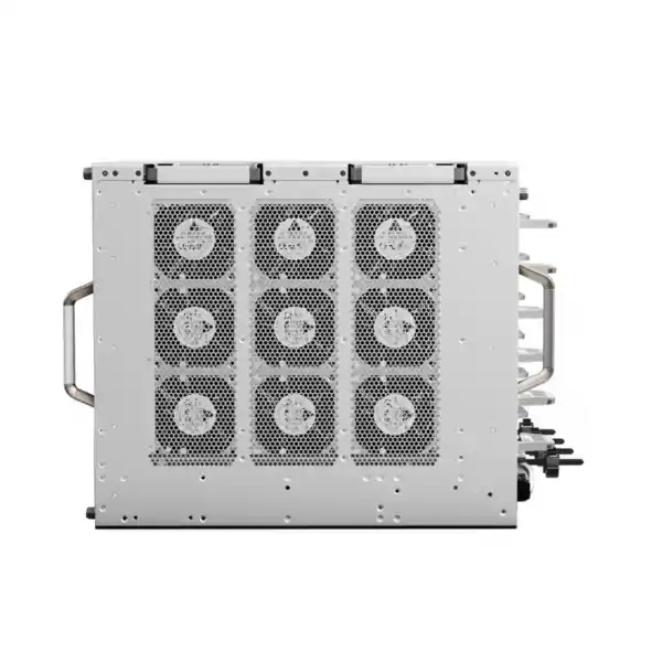
| Cooling | Single tray with 9 redundant fans; side-to-side airflow | Rack placement and adjacent equipment airflow must be planned. |
| Rack size | 8RU | Requires substantial rack space compared with fixed switches. |
| Dimensions | 35.43 × 44.2 × 40.9 cm | Depth and service clearance should be checked before installation. |
| Operating environment | Up to 45°C at lower specified altitude; lower maximum at higher altitude | Cooling design should be based on the actual equipment-room environment. |
Supervisor choice: the most important configuration decision
The supervisor engine is not simply a management module. It is central to the performance profile and feature set of the completed C9606R system. Cisco supports both the C9600-SUP-1 and the newer C9600X-SUP-2 in the chassis. The two options serve different design priorities, so the correct selection should be based on interface speed, line-card compatibility, software-feature requirements, and expected growth rather than on headline throughput alone.
With C9600-SUP-1, the platform supports up to 2.4 Tbps of bandwidth per line-card slot. With C9600X-SUP-2, maximum slot bandwidth rises to 6.4 Tbps, enabling the chassis to support a much higher aggregate capacity and current high-speed line-card options. For networks planning dense 100G links or a 400G-ready core, Supervisor 2 is often the performance-oriented path. However, feature support is not identical across every supervisor and Cisco IOS XE release. Some features available on Supervisor 1 may have restrictions on Supervisor 2, and line-card compatibility also varies.
The practical rule is to design from requirements outward. List the exact services the core must provide—routing protocols, segmentation, high availability, encrypted links where required, telemetry, policy functions, automation, QoS behavior, and interface speeds—then validate those against the intended supervisor, line cards, and software release. A capacity-only comparison can produce a fast chassis that still misses an operational feature the network team depends on.
Line-card flexibility and port-speed planning
The four line-card slots are the reason many buyers consider a chassis platform. Rather than locking the network into one fixed interface mix, the C9606R can be populated with compatible cards selected for the links the core must terminate. Cisco’s current architecture supports interface families spanning copper multigigabit Ethernet and fiber-based 1G, 10G, 25G, 40G, 50G, 100G, 200G hardware-capable options, and 400G on appropriate combinations. The exact number of ports and supported speed on each slot depends on the installed line card and supervisor.
This makes the platform useful in phased migrations. A campus might begin with 10G or 25G access-switch uplinks and 40G or 100G inter-core connections, then introduce 50G, 100G, or 400G paths as access density, Wi-Fi backhaul, virtualization traffic, storage traffic, or application demand increases. The chassis does not force every link to be upgraded at once. Instead, capacity can be added by changing or adding line cards and optics, subject to compatibility and software requirements.
Port planning should include more than counting interfaces. Engineers should calculate oversubscription targets, uplink diversity, breakout requirements, optic types, fiber plant capability, connector standards, expected cable distances, spare-port policy, and failure domains. A design with enough total ports can still be weak if too many critical uplinks terminate on one line card or if the selected optical standard does not match the installed fiber infrastructure. A configuration review should therefore map each intended connection to a physical card, interface type, optic, cable path, and redundancy partner.
High availability inside one chassis
The C9606R provides two dedicated supervisor slots and is designed for supervisor redundancy. Cisco documents support for 1+1 redundant supervisor engines together with technologies such as Stateful Switchover and Non-Stop Forwarding in supported configurations. In practical terms, a dual-supervisor design can reduce the risk that a single supervisor failure removes the entire chassis from service. It also gives network teams a stronger foundation for software maintenance strategies than a single-control-plane design.
Redundancy is not automatic simply because the chassis has two supervisor slots. The bill of materials must include the second compatible supervisor, and software and operational procedures must be planned correctly. The same is true for power. The chassis has four PSU bays and supports combined or N+1 power modes, but a resilient power design depends on how many supplies are installed, their wattage, the source circuits feeding them, and the calculated demand of the chosen line cards and supervisors.
High availability should be treated as an end-to-end design property rather than a chassis feature. If both supervisor engines are installed but every upstream connection uses one line card, one fiber path, one rack PDU, or one building route, the system still contains large single points of failure. A good deployment distributes critical links, power feeds, cable routes, and logical adjacencies according to the organization’s recovery objectives and maintenance model.
Two-chassis resiliency with StackWise Virtual
For organizations that need chassis-level fault tolerance, Cisco supports StackWise Virtual on the Catalyst 9606R in supported software and hardware combinations. StackWise Virtual allows two physical switches to operate with a single logical control and management relationship for supported functions, while Multichassis EtherChannel can be used to connect downstream or upstream devices across both chassis. This can help reduce dependence on a single physical chassis when the design is implemented correctly.
A dual-chassis architecture is more demanding than adding a second box to a rack. The two chassis need appropriately designed virtual links, dual-active detection, diverse uplinks, consistent software and configuration management, and a clear plan for failure and maintenance events. The design must also account for the number and speed of ports consumed by the inter-chassis relationship. If the two chassis are installed in separate rooms or buildings, fiber distance, path diversity, latency, and physical security should be reviewed as part of the architecture.
Not every campus needs StackWise Virtual. Smaller environments may achieve their availability goals with in-chassis supervisor and power redundancy plus redundant routed links to other devices. Larger or more critical networks may benefit from two chassis. The right answer depends on acceptable downtime, maintenance windows, budget, physical topology, and the number of services that converge on the campus core.
Power architecture and UPS planning
The C9606R includes four power-supply bays and supports 3000W AC, 2000W AC, and 2000W DC power-supply options. Cisco documents both combined and N+1 modes. In combined mode, installed power supplies contribute toward the chassis power budget. In N+1 mode, capacity is planned so one supply can be reserved for redundancy. Power supplies used together are subject to compatibility and wattage rules, so a configuration should be calculated for the actual supervisor and line-card population rather than estimated from chassis size alone.
For a Tanzanian enterprise deployment, site power continuity is often as important as switch redundancy. The network team should document the source circuits, UPS capacity, generator or alternate-power strategy where used, PDU ratings, plug and cord requirements, and desired runtime during an outage. Critical redundant supplies should not all terminate on a single upstream electrical failure domain if the site architecture supports independent feeds. The switch can only provide useful power redundancy when the surrounding electrical design preserves that redundancy.
Power planning should also include future line-card additions. A configuration that operates comfortably with two supplies today may need a different supply population after high-density or higher-speed cards are installed. Reserve electrical and UPS headroom for the likely growth scenario, and verify the final design with the applicable Cisco power-planning resources before purchase and installation.
Rack space, airflow, and equipment-room readiness
At 8RU, the C9606R is a substantial chassis and needs more preparation than a 1RU fixed switch. Cisco lists chassis dimensions of approximately 35.43 cm high, 44.2 cm wide, and 40.9 cm deep. The documented weight with the fan tray and two AC power supplies is over 31 kg, before the final line-card and supervisor population is considered. Rack loading, installation handling, rails or shelf requirements, and service clearances should therefore be assessed before equipment arrives on site.
Cooling is side-to-side, not the front-to-back airflow pattern used by many servers and data-center switches. That detail can affect rack placement and containment strategy. The chassis uses a redundant nine-fan tray and is designed for serviceability, but the surrounding rack must allow the intake and exhaust path to remain clear. Dense cabling should not obstruct the side airflow or make fan-tray service impractical.
The published operating range is broad, but equipment rooms should still be engineered for stable conditions rather than relying on maximum limits. Verify actual room temperature under full electrical load, air-conditioning redundancy, dust control, rack grounding, cable management, fire-safety arrangements, and access control. In locations where cooling or utility power is less predictable, environmental monitoring and alerting can be as important to uptime as the switch’s internal redundancy features.
Cisco IOS XE, automation, and operational consistency
Catalyst 9600 Series switches run Cisco IOS XE, giving the C9606R a software foundation familiar to many enterprise network teams. The platform is positioned for modern campus operations, including programmable management, telemetry, automation, policy integration, and Cisco Catalyst Center workflows when the required licenses and software components are in place. This can be valuable where the core switch must fit into an existing Cisco Catalyst operational model rather than becoming a separate management island.
Software planning still requires discipline. Before deployment, the organization should identify the target IOS XE release, confirm that the selected supervisor and line cards are supported on that release, review any feature caveats, and define the upgrade path. High-speed hardware can expose operational problems if a required routing, QoS, security, or observability feature differs between supervisor generations or release trains. Current Cisco release notes should be part of the final design validation, especially for networks migrating from older Catalyst platforms.
The benefit of a modular enterprise core is greatest when operations are standardized around templates, configuration control, monitoring, backups, and documented change procedures. Buyers should therefore consider not only the hardware configuration but also how the platform will be onboarded into existing authentication, logging, NTP, DNS, monitoring, configuration archive, automation, and incident-response systems.
Routing, segmentation, and campus-core design
A campus core is not merely a fast Ethernet cross-connect. It often participates in Layer 3 routing, carries multiple VLAN or VRF segments, connects internet or WAN edge devices, aggregates access blocks, and provides the transport foundation for business services. The Catalyst 9600 family supports enterprise routing and segmentation capabilities through IOS XE, but the exact scale and feature behavior depend on the supervisor, software release, license, and configuration profile.
During design, decide whether the C9606R will operate as a traditional Layer 3 core, as part of a collapsed core, as a distribution switch, or as a platform integrated into a broader Cisco campus architecture. That role determines how many routed adjacencies, VLANs, VRFs, EtherChannels, access blocks, and policy boundaries it must handle. It also affects whether links should be Layer 2 trunks, routed point-to-point connections, or part of an overlay or fabric design.
For a new network, routed access can simplify failure domains and reduce spanning-tree dependence in some designs. For an existing campus, migration may require retaining Layer 2 services while introducing newer routing and segmentation methods gradually. The C9606R gives the physical flexibility to support substantial interface density, but a successful migration still needs a logical design that documents gateway placement, first-hop redundancy where applicable, route summarization, failure convergence, multicast requirements, QoS policies, and dependencies on legacy systems.
Security considerations: validate by supervisor and software release
Enterprise core switches are central enforcement and visibility points, but security feature names should not be assumed to work identically across every hardware generation. Cisco’s current release documentation shows that some security capabilities have restrictions on the C9600X-SUP-2 compared with other Catalyst 9600 configurations. This is an important reason to validate the final hardware and software combination against the organization’s actual policy requirements before purchase.
If the design depends on features such as MACsec, port-based controls, specific ACL behaviors, TrustSec functions, or other hardware-assisted security services, map each requirement to the intended supervisor and line card. The newest or fastest supervisor is not automatically the correct choice for every policy model. Conversely, organizations that prioritize very high slot bandwidth and 400G connectivity may accept or redesign around some feature differences to achieve their performance objectives.
Security planning should also cover management-plane protection. Use role-based administrative access, centralized authentication where appropriate, secure management protocols, logging, configuration backup, SNMP or telemetry protection, software image management, and restricted out-of-band or management access. The chassis should be deployed as part of a controlled operational system, not as an isolated device configured once and then left unmanaged.
Migration from an older campus core
The C9606R is often evaluated when an organization has outgrown an older modular platform or has reached the practical limits of fixed switches used as a campus core. Migration should begin with an inventory of the current environment: interface counts and speeds, optical modules, fiber types, VLANs, routed networks, first-hop redundancy, EtherChannels, spanning-tree roles, multicast, WAN handoffs, firewalls, wireless controllers, server connections, network services, and every dependency that terminates on or passes through the existing core.
That inventory should then be mapped to the target C9606R slots. Critical links can be distributed across line cards, and capacity can be reserved for expansion. The project team should identify which optics and cabling can be reused and which must change because of interface type, speed, connector, or reach. Where 40G or 100G links are being upgraded, confirm that the installed fiber plant supports the selected transceivers and that both ends of each connection use compatible standards.
A staged cutover is usually easier to manage than a single undocumented change. Build and test the new chassis configuration, validate routing and management reachability, pre-stage uplinks where the topology allows it, establish a rollback plan, and migrate logical services in a defined order. For high-availability environments, failure testing should be included before production acceptance: supervisor switchover, power-supply loss, link failure, line-card impact, routing reconvergence, and—where used—StackWise Virtual failure scenarios.
Capacity planning: buy for the traffic model, not the label
A chassis capable of 25.6 Tbps does not mean every deployment needs—or automatically receives—that level of usable performance. The practical capacity depends on supervisor selection, line cards, port speeds, traffic distribution, and the forwarding features enabled in the real configuration. Capacity planning should begin with current traffic measurements and realistic growth assumptions. Identify peak utilization on access uplinks, data-center or server connections, WAN edges, internet firewalls, wireless aggregation, backup windows, video traffic, collaboration systems, and any large east-west flows between campus segments.
Then model failure conditions. A link bundle that runs at 45 percent during normal operation may exceed safe utilization if one member fails. Similarly, a pair of distribution blocks can place unexpected load on the surviving path during maintenance. The chassis should be sized for degraded-mode operation, not only for average traffic. This is especially important when hundreds or thousands of users depend on a small number of core links.
Growth planning should distinguish between port-count growth and bandwidth growth. Adding more users may require more access uplinks, while newer Wi-Fi generations, virtualization clusters, IP video, backups, or application consolidation may increase the speed needed on existing links. A modular platform is attractive because these two growth patterns can be addressed with different line-card choices, but only if spare slots, power headroom, optics strategy, and fiber capacity are considered at the start.
Common deployment scenarios
Large enterprise campus core
Aggregate multiple distribution or access blocks into a modular, high-capacity core with redundant supervisors and power, using the port mix appropriate for the campus backbone.
Collapsed core and distribution
Use the chassis as a combined Layer 3 aggregation and core platform when the topology benefits from fewer tiers but still needs substantial interface density and resilience.
Education or multi-building campus
Terminate high-speed fiber uplinks from buildings or access zones while reserving modular expansion for future bandwidth and additional distribution blocks.
Core refresh and migration
Replace an older modular core with a platform that supports current IOS XE operations, higher-speed interfaces, and a growth path toward denser 100G or 400G connectivity.
High-availability two-chassis design
Deploy a pair of C9606R systems using a supported dual-chassis architecture when business continuity objectives justify chassis-level redundancy.
High-speed aggregation
Consolidate many 10G, 25G, 40G, 50G, or 100G connections and introduce higher-speed 400G paths where the supervisor, line card, optics, and peer devices support them.
When a smaller fixed switch may be a better fit
The C9606R is powerful, but it is not automatically the best choice for every network. A smaller fixed-form-factor Catalyst switch may be more appropriate when the required port count is modest, the organization can tolerate device-level replacement rather than field-replaceable modules, 8RU of rack space is difficult to justify, or the traffic profile does not need a modular high-capacity core. Fixed switches can also simplify procurement because the interface mix and power design are more predetermined.
The modular chassis becomes more compelling when interface requirements are diverse, core uptime matters, supervisors or line cards need redundancy or replaceability, multiple high-speed uplinks are expected, or future growth is difficult to predict. It can also reduce the number of individual boxes required in a large aggregation layer, although that consolidation increases the importance of designing chassis and path redundancy correctly.
A useful comparison should therefore include at least three options: a single modular C9606R design, a redundant pair of C9606R chassis, and a fixed-switch alternative sized for the same port and resiliency requirements. Comparing only purchase price misses differences in rack space, optics, power, spare strategy, operational complexity, growth capacity, and failure domains.
What to provide when requesting a C9606R configuration
A precise quotation is easier when the buyer provides a short network requirement rather than asking for the chassis alone. The most useful input is a table of connections showing interface speed, media type, quantity, peer device, and required redundancy. If the project is a migration, include the current core model, installed line cards, and the list of services that depend on it.
- Number of 1G, 10G, 25G, 40G, 50G, 100G, 200G, and 400G links required now and later.
- Copper versus fiber interfaces, optic type, connector type, and approximate link distance.
- Need for one or two supervisor engines and one- or two-chassis redundancy.
- Required routing, segmentation, security, QoS, monitoring, and automation features.
- Rack space, rack depth, power source, UPS architecture, and equipment-room cooling constraints.
- Existing Cisco software environment and intended Catalyst Center or management integration.
- Target software release, maintenance policy, support expectations, and spare-parts strategy.
This information allows the configuration to be checked for supervisor compatibility, slot usage, power budget, optics, software requirements, and resilience before procurement. It also reduces the risk of receiving a chassis that cannot be commissioned because one necessary module, power supply, license, or transceiver was omitted.
Tanzania deployment checklist
For a deployment in Tanzania, treat the switch as part of the site infrastructure rather than a device to be installed in isolation. Confirm the actual equipment-room conditions and the path between the core and the buildings, access switches, WAN edge, internet edge, firewalls, wireless infrastructure, and servers it will connect. Where inter-building fiber is used, document route diversity and the exact fiber type and available cores before selecting optics.
Size UPS and upstream electrical protection for the final populated chassis, not only the empty chassis. Preserve separate failure domains where the site electrical design allows.
Maintain clear side airflow, verify cooling under peak load, and keep the rack environment clean enough for long-term fan and module reliability.
Match optics to distance, connector, fiber type, peer interface, and desired speed. Do not assume an existing 10G path can be upgraded to 100G without fiber verification.
Predefine management addressing, monitoring, logging, authentication, backups, alerting, and the escalation path for hardware or software faults.
Configuration and procurement guidance
Cisco’s ordering documentation lists C9606R as the Catalyst 9600 Series six-slot chassis and then treats supervisors, line cards, power supplies, software subscriptions, and accessories as separate configuration elements. This means a correct quotation needs to be assembled as a solution. The chassis product number alone does not describe the final switching capacity, number of usable ports, or redundancy level.
The best procurement process is to freeze a logical design before the bill of materials is approved. Decide the supervisor generation, required number of supervisors, line cards and slot locations, PSU type and count, software term, optics, spare policy, and rack accessories. Then validate that every module is compatible with the intended IOS XE release and that the power budget is adequate. If the design includes 200G or 400G links, check both ends of the link and the exact transceiver support matrix.
Do not use third-party list prices or generic online stock claims as a substitute for a Tanzania-specific quotation. Final pricing and availability can vary by configuration, software term, support choice, sourcing route, and project timing. Request a current quote for the exact bill of materials after the technical configuration is agreed.
Frequently asked questions
Is the Cisco C9606R a complete switch?
No. C9606R is the six-slot chassis foundation. A functional deployment requires compatible supervisor, line card, power-supply, software, and connectivity selections. The final system should be quoted as a complete configuration rather than as the chassis part number alone.
How many line cards does the C9606R support?
The chassis provides four line-card slots. Slots 1, 2, 5, and 6 are used for line cards, while slots 3 and 4 are dedicated to supervisor engines. The exact supported cards depend on the supervisor and software combination.
Can the C9606R use redundant supervisors?
Yes. The chassis has two supervisor-engine slots and supports redundant supervisor designs. A second supervisor must be included in the configuration, and the intended high-availability behavior should be validated against the selected supervisor and IOS XE release.
What is the maximum switching capacity?
Cisco specifies up to 25.6 Tbps of wired switching capacity for the C9606R chassis with the appropriate Supervisor 2 architecture, with up to 6.4 Tbps per line-card slot. A Supervisor 1 configuration has a lower maximum per-slot bandwidth of up to 2.4 Tbps.
Does it support 400 Gigabit Ethernet?
The Catalyst 9600 platform supports 400G interfaces on compatible Supervisor 2 and line-card combinations. 400G capability is not created by the empty chassis alone, so the exact line card, transceiver, peer device, fiber, and software support must be selected and validated.
How many power supplies can be installed?
The chassis has four power-supply bays and supports current 3000W AC, 2000W AC, and 2000W DC options. The required quantity depends on chassis load, input power, and whether the design uses combined or N+1 redundancy mode.
Can two C9606R chassis operate as a resilient pair?
Cisco supports StackWise Virtual on the C9606R in supported configurations, allowing two physical chassis to participate in a virtualized switching design with technologies such as Multichassis EtherChannel. The exact topology should be engineered against the current Cisco hardware and software guidance.
Is C9606R suitable for a small office?
Usually it is intended for larger campus core or distribution requirements. A small office with modest port counts and bandwidth needs may be better served by a smaller fixed Catalyst switch. The C9606R becomes attractive when modular expansion, high-speed aggregation, and component redundancy justify the larger chassis.
Request a C9606R configuration review
Before ordering, define the number and speed of links, supervisor redundancy, line-card mix, power design, optics, rack constraints, and software requirements. A configuration review helps turn the C9606R chassis into a complete, compatible core-switching solution sized for your Tanzania deployment.
Next step: send your current core model, required uplink speeds, port counts, preferred redundancy level, and a simple network diagram so the bill of materials can be checked before quotation.
Reviews
There are no reviews yet.