
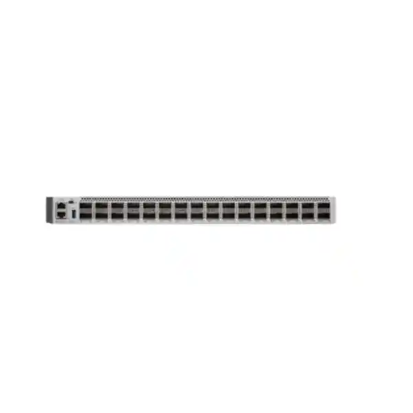
Cisco enterprise core switching
Cisco Catalyst C9500-32C Network Switch for High-Density 40/100G Core and Distribution
The Cisco Catalyst C9500-32C is designed for organizations that need a compact, high-capacity fiber switching platform at the center of a campus or large enterprise network. With 32 QSFP28 ports supporting 40 Gigabit Ethernet and 100 Gigabit Ethernet, the switch can consolidate fast building uplinks, distribution blocks, data-center interconnects and high-bandwidth services while keeping the core in a fixed 1RU form factor.
Up to 6.4 Tbps switching
Up to 2 Bpps forwarding
Cisco UADP 3.0
For a Tanzania deployment, the key buying question is not simply whether the chassis is fast enough. A successful design also depends on the correct Cisco software license, validated QSFP28 or QSFP+ optics, fiber type and distance, rack power, cooling, redundancy plan and an implementation method that fits the existing network. FourTeck Tanzania can use those requirements as the basis for a configuration review before the final bill of materials is selected.
Best fit
Large campus core and distribution layers, high-density 40/100G aggregation, resilient enterprise backbones and environments moving from 40G toward 100G.
Port profile
Thirty-two fixed QSFP28 interfaces support 40G and 100G operation. Cisco also documents breakout options that can increase 10G or 25G port density in supported designs.
Resilience
Dual power-supply bays, field-replaceable fans and StackWise Virtual support make the platform suitable for architectures where maintenance and component failure should not force a complete core outage.
Important planning point
Optics, fiber, licensing, software release, power and airflow are deployment-specific. They should be confirmed as part of the final configuration rather than assumed from the chassis model alone.
Why enterprises choose a 100G-ready campus core
As wireless access, virtualization, cloud applications, video, surveillance, IP communications, data analytics and backup traffic grow, the aggregation layer can become the place where many smaller links compete for the same upstream capacity. A 100G-capable core provides room to aggregate multiple access and distribution blocks without creating an immediate uplink bottleneck. This is especially useful for organizations that operate several buildings, large floors, data-intensive departments, server rooms or geographically concentrated facilities connected by campus fiber.
The C9500-32C is positioned by Cisco as a high-density fiber model for campus core and distribution. That positioning matters because it is not intended to replace a typical copper access switch that directly powers phones, cameras or wireless access points. Instead, it belongs higher in the hierarchy, where fast fiber interfaces connect other switches, routing domains and major network services. Buyers should therefore compare it against the required backbone topology rather than against access-layer port count alone.
A 32-port 100G-capable platform can also simplify growth planning. An organization may begin with a mixture of 40G and 100G links, then migrate selected uplinks as traffic and optics budgets justify the change. This can reduce the need to replace the central chassis merely because the next distribution refresh moves to faster interfaces. The final value, however, depends on choosing compatible optics, cabling and remote devices, so the migration path should be designed end to end.
Key verified specifications
| Model | Cisco Catalyst C9500-32C |
|---|---|
| Primary role | Fixed enterprise campus core and distribution switching |
| Front-panel network ports | 32 × QSFP28 supporting 40G/100G Ethernet |
| Switching capacity | Up to 6.4 Tbps |
| Forwarding rate | Up to 2 Bpps |
| ASIC | Cisco UADP 3.0 architecture |
| Form factor | 1 rack unit |
| Dimensions | 1.73 × 17.5 × 21.2 in. (4.39 × 44.45 × 53.85 cm) |
| Weight | 25.64 lb (11.63 kg) for the documented chassis configuration with two power supplies and built-in fan |
| Input voltage | 90 to 264 VAC for the AC-powered platform specification |
| Operating temperature | 0°C to 40°C up to 10,000 ft under the documented operating specification |
| Minimum software requirement | Cisco IOS XE 16.8.1a for this model; production software selection should follow Cisco’s current recommended-release guidance and feature requirements. |
32 QSFP28 ports: what that means in a real design
The front panel provides 32 QSFP28 interfaces, and Cisco specifies both 40G and 100G port density of 32 for the standalone C9500-32C. This gives a network architect substantial flexibility when the existing environment includes 40G distribution links but the target design is moving toward 100G. The same chassis can support a mixed migration strategy where appropriate, provided the optics, cabling, interface configuration and software support are all compatible.
Cisco also documents breakout port density of up to 96 ports at 10G and up to 96 ports at 25G for this model using supported breakout cabling and configurations. Breakout is useful when a dense set of lower-speed fiber connections must be aggregated into the core without dedicating a full 100G port to every peer. It should not be treated as a universal guarantee that every interface can be broken out in every topology or software scenario. The exact supported port groups, transceivers, cables and interface modes should be checked against Cisco’s current compatibility and configuration documentation.
For procurement, the chassis part number is only one element of the bill of materials. A complete design may also require QSFP28 100G optics, QSFP+ 40G optics, breakout assemblies, single-mode or multimode fiber components, patching, spare optics and compatible transceivers on the devices at the far end. Fiber distance, connector type, wavelength and optical budget should be validated before ordering because a physically compatible form factor does not automatically mean the link will operate over the installed fiber plant.
Performance for aggregation-heavy networks
Cisco rates the C9500-32C at up to 6.4 Tbps of switching capacity and up to 2 billion packets per second of forwarding. Those figures align with the platform’s role as a high-throughput aggregation point. In practical terms, the switch is built to move traffic among many high-speed interfaces without relying on a low-capacity shared uplink architecture. This is important when the core must simultaneously carry user traffic, server traffic, backups, voice, video, wireless aggregation and inter-VLAN routing.
The platform uses two UADP 3.0 ASICs. Cisco’s architecture material explains that UADP 3.0 platforms use a unified buffering approach designed to improve burst absorption compared with older architectures where buffering was divided differently. Buffer behavior is only one part of congestion design, however. QoS policy, oversubscription, traffic mix, microbursts and the speed relationship between ingress and egress interfaces all influence application experience. A high headline switching capacity therefore does not eliminate the need for careful traffic engineering.
When sizing a core, it is useful to calculate expected east-west and north-south traffic, the number of active uplinks, peak utilization, failure-state utilization and growth over the lifecycle of the deployment. A design that looks comfortable under normal conditions may become congested after one member of a redundant pair or one path fails. Planning the C9500-32C for both normal and degraded states helps ensure that the available 40G or 100G links are used in a way that supports business continuity rather than simply maximizing interface count.
High availability with StackWise Virtual
Cisco StackWise Virtual allows two supported Catalyst 9500 switches to operate as a virtualized system for higher availability and simplified topology. On the C9500-32C, Cisco documents support for StackWise Virtual and multi-chassis EtherChannel, allowing downstream or upstream devices to form port channels across both members. This can reduce dependence on spanning-tree reconvergence and can provide an active use of links that might otherwise sit idle in a traditional dual-core design.
There is an important model-specific restriction: on the C9500-32C, Cisco states that StackWise Virtual Links and Dual Active Detection links are configured on front-panel interfaces 1 through 16. Current software documentation should be checked before implementation because supported behavior can depend on release and interface mode. The design should also reserve sufficient bandwidth for the virtual links, place Dual Active Detection correctly and protect the physical paths from a common failure where possible.
StackWise Virtual is not a substitute for an overall resilience plan. Power feeds, rack placement, fiber routes, upstream services, routing, maintenance procedures and software upgrade strategy still matter. In a Tanzanian enterprise environment, it is also prudent to assess the quality and continuity of facility power and the capacity of UPS or generator systems that support the network room. Those facility considerations are site-specific and should be verified during deployment planning rather than assumed from the switch specification.
Power, cooling and rack planning
The C9500-32C is a 1RU switch, but its depth and power profile require proper rack planning. Cisco lists dimensions of approximately 4.39 cm high, 44.45 cm wide and 53.85 cm deep. Space should be allowed for rear power connections, cable bend radius, airflow and service access. Dense QSFP cabling at the front can become difficult to manage if patching is not organized, so horizontal or vertical cable management may be needed depending on the rack layout.
Cisco documents dual power-supply bays with 1+1 redundancy support. For the C9500-32C specifically, the supported supply family includes 1600W AC and 1600W DC options. Cisco also notes that the switches can operate with one power supply in nonredundant mode, while two supplies can be used for redundant load sharing. The exact input, cord, PDU and feed arrangement should be designed for the site. If true power redundancy is required, the two supplies should not simply terminate on the same single point of failure.
Cooling also deserves attention. Cisco identifies the C9K-T2-FANTRAY family for this model and documents five field-replaceable fan modules with front-to-back airflow. The chassis can continue operating with one individual fan failure, but a failed fan should be replaced promptly because additional fan loss can force a protective shutdown. Network rooms should therefore maintain suitable environmental conditions and should avoid blocking inlet or exhaust paths.
Cisco’s operating specification lists 0°C to 40°C up to 10,000 feet under the published conditions, with altitude-related considerations at higher temperature. A deployment in a warm equipment room should be assessed based on actual inlet temperature rather than general building temperature. Air conditioning, rack density, UPS heat output and dust management can all affect the operating environment.
Security and segmentation capabilities
At the enterprise core, security is not limited to firewall placement. The switching platform must support segmentation, policy enforcement, secure management and visibility so that traffic can be controlled as it moves between network zones. The Catalyst 9500 family is designed for enterprise routing and switching functions that include access-control lists, quality-of-service policy, telemetry and Cisco software-defined campus capabilities depending on software and licensing.
Cisco documents hardware support on the high-performance Catalyst 9500 family for line-rate 256-bit IEEE 802.1AE MACsec and WAN-MACsec encryption. MACsec can protect Ethernet traffic on supported links, which is valuable when fiber crosses shared pathways, buildings or other areas where link confidentiality is required. Feature combinations and restrictions vary by software release and topology, so encryption should be validated against the exact intended interface mode, SD-Access design and peer device.
The platform also supports Cisco TrustSec-related capabilities and security group-based segmentation as part of suitable Cisco architectures. Organizations considering these features should define the identity source, policy model, control-plane dependencies and operational ownership before deployment. A segmentation project succeeds when the policy is understandable and maintainable, not merely because the hardware can carry tags or enforce access rules.
Management-plane hardening should be part of the implementation baseline as well. Recommended practices commonly include controlled administrative access, centralized authentication, role separation, secure management protocols, logging, time synchronization, configuration backup and software lifecycle management. The exact standard should match the organization’s security policy and the Cisco IOS XE release used in production.
Routing, table scale and SDM templates
Core switches often need to carry more than Layer 2 VLANs. The C9500-32C is built for Layer 3 enterprise routing and supports configurable resource allocation through Cisco Switch Database Management templates. Cisco publishes different template profiles for distribution, core, NAT and SD-Access use cases on the high-performance Catalyst 9500 models. These templates allocate hardware resources differently among routes, MAC addresses, ACL entries, QoS entries, NetFlow resources, tunnels and other functions.
This matters because a specification such as “up to” a certain number of routes or MAC addresses is not a promise that all maximum scale values can be achieved simultaneously. Hardware resources are shared, and the selected template influences how they are allocated. A network with many routed prefixes may prefer a different profile from a large Layer 2 aggregation environment, while an SD-Access fabric may need a template aligned with LISP and policy functions.
Before procurement, it is worth estimating the number of IPv4 and IPv6 routes, connected hosts, multicast groups, VLANs, ACL entries, security group tags and telemetry flows that the core must support. This is particularly important during mergers, campus consolidation or service-provider-style enterprise designs where table sizes can grow unexpectedly. If the existing network already approaches platform limits, the design should be reviewed against Cisco’s current scale documentation for the intended IOS XE release.
For most conventional enterprise campuses, the key benefit is flexibility: the C9500-32C is not locked into a single Layer 2-only role. It can provide routed core functions, high-speed aggregation and policy enforcement in one fixed platform, subject to the selected software tier and feature design.
Cisco IOS XE and licensing: confirm the edition before ordering
Cisco lists C9500-32C ordering variants associated with Network Essentials and Network Advantage licensing. The chassis may look identical while the software entitlement and available feature set differ, so a quote should identify the intended license level rather than treating “C9500-32C” as a complete order definition. Cisco has also evolved its networking subscription and licensing approach over time, which makes it important to validate the current commercial model at the time of purchase.
The minimum software requirement published by Cisco for this model is IOS XE 16.8.1a, but that is a platform introduction baseline rather than a recommendation to deploy an old release today. Production software should be selected from current supported and recommended trains according to the required features, security advisories, hardware compatibility, operational policy and support lifecycle. Organizations should also confirm whether a new switch must integrate with Cisco Catalyst Center, SD-Access, telemetry collectors, authentication infrastructure or other management systems.
Licensing should be mapped to actual requirements such as advanced routing, segmentation, automation or assurance rather than purchased by habit. Where a feature depends on a specific license or subscription, that dependency should appear explicitly in the bill of materials. This reduces the risk of installing the hardware only to discover that the intended network function requires a different entitlement.
Optics and fiber planning for Tanzania deployments
A 40/100G switch is only as useful as the optical design around it. Tanzanian enterprises may have a mixture of newer single-mode backbone fiber, older multimode links, campus ducts, leased dark fiber or carrier-provided Ethernet handoffs. The correct transceiver depends on the actual medium, distance, connector, fiber quality and remote interface. It is therefore better to begin with a link schedule than with a generic quantity of 100G optics.
For each intended connection, document the source device, destination device, required speed, approximate route length, fiber type, connector presentation, number of available strands and any intermediate patch panels. Then select Cisco-supported optics or cables that match both ends. For multimode infrastructure, the fiber category and distance can determine whether a particular optic is viable. For single-mode links, wavelength and reach are important, and longer campus routes may require a different optical class from a short equipment-room connection.
Breakout designs need extra care because one QSFP interface can fan out into multiple lower-speed connections only under supported combinations. The far-end interfaces, breakout cable or optical method, port grouping and software configuration must all align. Labeling is also critical: a single high-density front-panel port can represent several logical links, so patching documentation should clearly identify both the parent port and each breakout member.
If the backbone crosses buildings, include physical resilience in the design. Two logical links are not truly redundant if both fibers share the same duct, tray, patch panel or power-dependent intermediate device. Where business continuity requires diverse paths, route diversity should be verified on site.
Common deployment scenarios
Large campus core
Use a resilient pair to aggregate distribution switches from multiple buildings or zones. High-speed routed links and multi-chassis EtherChannel can reduce dependence on a single physical switch while keeping a compact footprint.
40G-to-100G migration
Retain selected 40G links while introducing 100G connections for the busiest distribution blocks, servers or interconnects. This can provide a staged upgrade path when replacing every remote device at once is not practical.
High-density fiber aggregation
Aggregate many high-speed fiber connections where rack space is limited. Breakout options can support additional 10G or 25G connectivity when validated against the exact supported port and transceiver combination.
Routed distribution
Use Layer 3 links to access blocks or service zones to reduce large Layer 2 failure domains. Routing policy, redundancy and convergence should be designed around application requirements and operational skill sets.
Secure backbone links
Where supported by the full design, MACsec can encrypt Ethernet links between capable peers. This can be relevant when backbone fiber traverses locations that require stronger link-layer confidentiality controls.
Campus consolidation
Consolidate several legacy aggregation devices into a smaller number of high-capacity platforms, provided port count, routing scale, fault domains and maintenance windows are carefully planned before migration.
Where the C9500-32C may not be the right fit
The C9500-32C is powerful, but not every network needs 32 ports of 40/100G capacity. A smaller distribution layer with mostly 1G, 10G or 25G connections may be better served by another Catalyst 9500 model with a more suitable native port mix. Buying excessive high-speed density can increase optics and power costs without improving user experience if the rest of the network cannot use the capacity.
It is also not an access switch for directly powering PoE endpoints. Organizations that need copper user ports, PoE for access points, cameras or phones, or large numbers of 1G edge connections should use appropriate access-layer switching and then uplink that layer to the C9500-32C. Separating access and core roles generally makes the design easier to scale and troubleshoot.
For environments that need 400G interfaces or substantially newer core silicon, Cisco’s Catalyst 9500X family may be more appropriate. Conversely, if 100G is required only on a few uplinks, a model with 25G access-facing density and a smaller number of 100G uplinks may align better with the topology. The correct model is therefore the one that matches the actual port-speed distribution, not simply the highest aggregate bandwidth.
A product review should also consider lifecycle and software support. Even when a hardware model remains orderable or supported, the chosen software train, optics and licenses each have their own lifecycle. Procurement should use current Cisco documentation at the time of purchase.
C9500-32C vs. nearby Catalyst 9500 options
Cisco offers several high-performance Catalyst 9500 models with different native port profiles. The comparison below is intended to help buyers frame the decision; final selection should be validated against current Cisco ordering and licensing information.
| Model | Native port profile | Typical decision point |
|---|---|---|
| C9500-32C | 32 × 40/100G QSFP28 | Choose when high 100G density is the main requirement. |
| C9500-32QC | 32 × 40G or a lower density of 100G operation depending on mode | Consider when 40G density is more important than 32 native 100G ports. |
| C9500-48Y4C | 48 × 1/10/25G plus 4 × 40/100G uplinks | Consider when many 10G/25G connections are needed with a smaller number of 100G uplinks. |
| C9500-24Y4C | 24 × 1/10/25G plus 4 × 40/100G uplinks | Consider for a lower-density 10G/25G distribution design. |
Migration planning from an existing core
Replacing a core switch has a larger operational impact than replacing a single access switch because many VLANs, routes, services and uplinks converge on the core. A structured migration should begin with discovery. Document every physical link, logical interface, VLAN, routed adjacency, first-hop redundancy protocol, port channel, spanning-tree relationship, multicast dependency, ACL, QoS policy, management service and monitoring integration that exists on the old platform.
Next, decide whether the new design will reproduce the old topology or use the opportunity to simplify it. Moving from Layer 2 trunks to routed access or distribution links may reduce fault domains, but it changes addressing and routing. Introducing StackWise Virtual may simplify multi-chassis connectivity, but it requires a deliberate SVL and DAD design. Migrating from 40G to 100G can change optics and fiber requirements even if the physical route remains the same.
A staged migration plan should identify preconfiguration tasks, test criteria, rollback conditions and the exact sequence of link moves. Where possible, validate software, optics and basic configuration on the new chassis before the maintenance window. Save current configurations and operational state from the legacy core so that routes, neighbors, MAC learning, port channels and monitoring behavior can be compared after cutover.
After migration, performance validation should include more than simple ping tests. Confirm expected routing adjacencies, redundancy state, link utilization, error counters, QoS behavior, monitoring, logging, authentication, time synchronization and application reachability. This reduces the chance that a hidden dependency becomes a later incident.
Operational considerations after deployment
A high-performance core benefits from disciplined operations. Configuration backups should be automated or performed regularly, and changes should be traceable. Monitoring should cover interface utilization, errors, optical levels where available, CPU, memory, temperature, fan and power-supply status, routing neighbors, StackWise Virtual state and key application paths. Capacity alerts are more useful when they trigger before links are persistently saturated.
Software maintenance is equally important. Cisco publishes IOS XE release notes, security advisories and lifecycle information that should be reviewed as part of a regular patch and upgrade process. Because the core carries a large percentage of organizational traffic, software changes should be tested and scheduled with rollback planning. In a redundant design, the expected behavior during upgrade or member restart should be understood before maintenance begins.
Spare strategy should reflect the business impact of a failure. Depending on organizational requirements, this may include spare optics, breakout cables, fan modules or power components. A complete spare chassis may be justified for some critical environments but not others. The decision should consider supplier lead time, support contract, business continuity objectives and how quickly traffic can be rerouted to another site or platform.
Documentation should be kept current. Port descriptions, rack diagrams, fiber-path records, IP addressing, routing design, licensing records and software baselines reduce troubleshooting time and make future upgrades safer. This operational discipline often delivers as much value as the raw hardware performance.
Pre-order checklist
Frequently asked questions
Does the C9500-32C really provide 32 ports of 100G?
Yes. Cisco’s current Catalyst 9500 data sheet lists the C9500-32C as a high-performance 32-port 100 Gigabit Ethernet switch using QSFP28 interfaces, with 32-port density at both 40G and 100G. The optics and peer devices must still support the intended speed.
Can the switch connect to 10G or 25G devices?
Cisco documents breakout port density of up to 96 ports at 10G and up to 96 ports at 25G on this model. Breakout support depends on the exact cable or optics, port grouping, software and configuration, so the proposed link design should be checked before procurement.
Is this switch suitable for a campus core?
Yes. Cisco positions the Catalyst 9500 family as its fixed enterprise core and aggregation switching platform, and specifically describes the C9500-32C as a high-density fiber model for campus core and distribution use.
Does it support StackWise Virtual?
Yes. Cisco documents StackWise Virtual support for the C9500-32C. On this model, current documentation identifies ports 1 through 16 as the interfaces used for StackWise Virtual Link and Dual Active Detection configuration, subject to the supported software and design rules.
Does the chassis include redundant power supplies?
The platform supports two power-supply bays and 1+1 redundancy, but the exact ordered configuration must be checked. Cisco documentation notes that Catalyst 9500 switches may ship with one supply by default and a second can be ordered for redundancy. Do not assume the quote includes two supplies unless it is explicitly listed.
Which power supply is used by the C9500-32C?
Cisco’s current hardware documentation lists 1600W AC and 1600W DC power-supply options for this specific model. The correct option depends on the site power design and should be included explicitly in the bill of materials.
Can it be used as a PoE access switch?
No. This is a high-speed fiber core and distribution platform, not a copper PoE edge switch. Access points, IP phones, cameras and user devices would normally connect to access-layer switches that uplink to the core.
What should be confirmed before requesting a quote in Tanzania?
Provide the desired port speeds, link distances, fiber type, remote switch models, redundancy requirement, preferred AC or DC power, software features and expected management platform. This allows the chassis, licensing, optics and resilience components to be reviewed as one solution instead of quoting an incomplete base unit.
Buying guidance for Tanzanian organizations
For businesses, universities, financial institutions, healthcare groups, hospitality operators, public-sector environments and other organizations with large campus networks, the C9500-32C can provide a strong foundation when the backbone genuinely requires high-density 40/100G fiber. The most important step is to translate business requirements into a complete technical bill of materials rather than purchasing the chassis in isolation.
A useful requirements package includes the current network diagram, desired target topology, approximate traffic levels, existing fiber inventory, rack and power details, required routing protocols, segmentation needs, management tools and resilience objectives. From there, the model can be checked against port density, licensing and optics. Where the existing network is mixed-vendor or uses older transceivers, compatibility should be validated carefully.
Pricing, stock availability, warranty terms, delivery times and local service arrangements can change and should be confirmed in the actual quotation. They are intentionally not assumed on this page. The objective is to help buyers identify the right technical configuration first, then obtain commercial details for that exact configuration.
Request a C9500-32C configuration review
Share your required 40G/100G links, fiber distances, peer devices, redundancy goals, power preference and Cisco feature requirements. FourTeck Tanzania can then prepare a configuration-oriented quotation request that accounts for the switch, appropriate licensing, compatible optics and the major resilience components your deployment needs.
Ask for a technical and commercial quote based on your actual topology.
Reviews
There are no reviews yet.